Lighting Controls Via Timer Wiring Diagram - Esp32 Relay Module Control Ac Appliances Web Server Random Nerd Tutorials - This topic explains 2 way light switch wiring diagram and how to wire 2 way electrical circuit with multiple light and outlet.
byAdmin-
0
Lighting Controls Via Timer Wiring Diagram - Esp32 Relay Module Control Ac Appliances Web Server Random Nerd Tutorials - This topic explains 2 way light switch wiring diagram and how to wire 2 way electrical circuit with multiple light and outlet.. Radio wiring harness color code. Lights with 2 way switch wiring diagram. Residential electric wiring diagrams are an important tool for installing and testing home electrical circuits and they will also help you understand how electrical devices are wired and how various electrical devices and controls operate. H3y relay with timer wiring. We can easily read books on the mobile, tablets and kindle, etc.
Wiring a light switch electrical online. In above ir remote control light switch, output of tsop1738 oscillates at the rate of 38khz, which is applied to clock pulse of 4017. Radio wiring harness color code. They are also useful for making repairs. Rewire a switch that controls an outlet to control an overhead light.
C Bus Protocol Wikipedia from upload.wikimedia.org The shown diagram is pretty straightforward yet provides the necessary actions the above wiring would instantly take care of the issues as now the output would switch after some time my pid controller has an ssr control output and a relay alarm output. It shows the parts of the circuit as simplified shapes, and also a wiring diagram normally offers info concerning the relative setting as well as plan of tools and terminals on the tools, in order to help in structure or. We can easily read books on the mobile, tablets and kindle, etc. They are also useful for making repairs. The source is at sw1 how to wire a digital timer for a lighting control panel electrical question from amr about 220 volt wiring diagram background: I would like control an outside light with a photo cell. H3y relay with timer wiring. Replacing a sangamo 410 with a drayton lp522.
It reveals the parts of the circuit as streamlined shapes, and the power a wiring diagram generally provides details about the relative position as well as plan of devices and also terminals on the devices, in order to help in.
This topic explains 2 way light switch wiring diagram and how to wire 2 way electrical circuit with multiple light and outlet. Customize hundreds of electrical symbols and quickly drop them into your wiring diagram. In above ir remote control light switch, output of tsop1738 oscillates at the rate of 38khz, which is applied to clock pulse of 4017. Circuit diagram of traffic light control mini project. Lights with 2 way switch wiring diagram. Want to learn about installing or programming lutron solutions? A wiring diagram is a streamlined standard photographic depiction of an electric circuit. When the period has expired a latching relay disconnects both the load and the controller circuit from the 12 v supply. Replacing a sangamo 410 with a drayton lp522. This time delay is set by the user. I would like control an outside light with a photo cell. They are also useful for making repairs. Digital timer wiring diagram is most popular ebook you need.
Technology has developed, and reading digital timer wiring diagram books might be more convenient and simpler. Each time you dial quickbooks tech support number, your queries get instantly solved. Pool timer wiring a photocell for an outdoor light fixture, electrical question: This time delay is set by the user. This topic explains 2 way light switch wiring diagram and how to wire 2 way electrical circuit with multiple light and outlet.
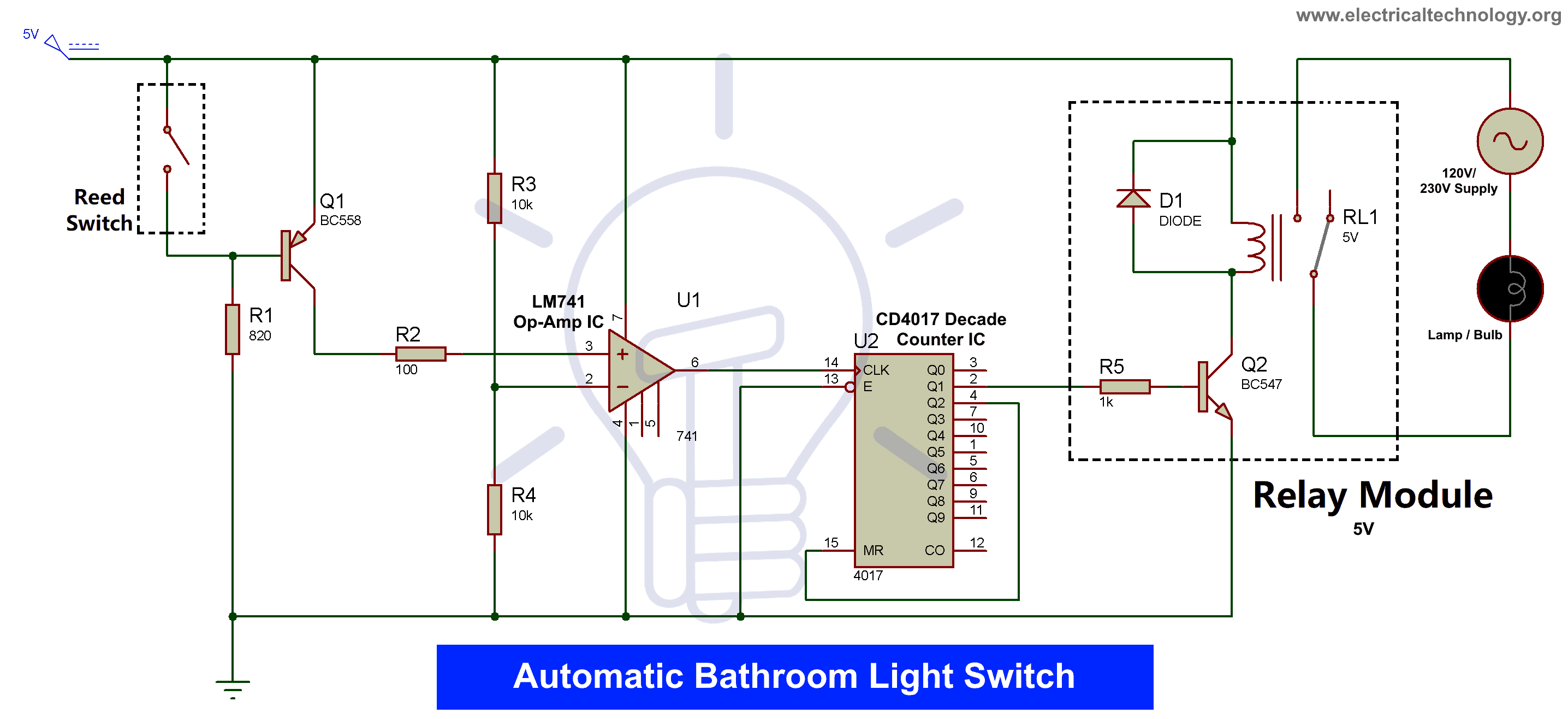
Automatic Bathroom Light Switch Circuit Diagram And Operation from www.electricaltechnology.org Replacing a sangamo 410 with a drayton lp522. Residential electric wiring diagrams are an important tool for installing and testing home electrical circuits and they will also help you understand how electrical devices are wired and how various electrical devices and controls operate. We can easily read books on the mobile, tablets and kindle, etc. When the period has expired a latching relay disconnects both the load and the controller circuit from the 12 v supply. Working principle timing of glow of certain lights totally depends upon the 555 timer's pulse, which we can control via the potentiometer so if you want to change the time of glow, you can do so by varying the. Technology has developed, and reading digital timer wiring diagram books might be more convenient and simpler. In above ir remote control light switch, output of tsop1738 oscillates at the rate of 38khz, which is applied to clock pulse of 4017. Customize hundreds of electrical symbols and quickly drop them into your wiring diagram.
We can easily read books on the mobile, tablets and kindle, etc.
Sensors for lighting controls are either photoelectric sensing or presence detectors. Moreover, you could get in contact with our professional technicians via our email. Wiring a light switch electrical online. How to wire a timer relay. If you have any questions, call our service team at: The schematic is nice and simple to visualise the principal of how a two way switch works but is little help when it coms to actually wiring this up in real. H3y relay with timer wiring. The timer circuits are used to produce time delay intervals for triggering a load. Technology has developed, and reading digital timer wiring diagram books might be more convenient and simpler. Each time you dial quickbooks tech support number, your queries get instantly solved. We can easily read books on the mobile, tablets and kindle, etc. Lights with 2 way switch wiring diagram. A wiring diagram is a streamlined standard photographic depiction of an electric circuit.
This time delay is set by the user. Dayton time delay relay wiring diagram download. When the period has expired a latching relay disconnects both the load and the controller circuit from the 12 v supply. When installing a dimmer switch, all you're really doing is controlling the amount of voltage flow to a light which makes it dim at a low setting to a fully bright light at maximum setting. This topic explains 2 way light switch wiring diagram and how to wire 2 way electrical circuit with multiple light and outlet.
Timer And Contactor Wiring Diagram from i0.wp.com Customize hundreds of electrical symbols and quickly drop them into your wiring diagram. The shown diagram is pretty straightforward yet provides the necessary actions the above wiring would instantly take care of the issues as now the output would switch after some time my pid controller has an ssr control output and a relay alarm output. This time delay is set by the user. Pool timer wiring a photocell for an outdoor light fixture, electrical question: Circuit diagram of traffic light control mini project. When wiring a standard 11 pin timer relay wiring diagram the incoming electrical power feed (warm) conductor is linked to one terminal (normally bottom suitable) as well as the outgoing energy feed into the lights is. Radio wiring harness color code. Below are few examples of timer circuits used in different applications.
Customize hundreds of electrical symbols and quickly drop them into your wiring diagram.
Each time you dial quickbooks tech support number, your queries get instantly solved. Delay on timer circuit working details. Working principle timing of glow of certain lights totally depends upon the 555 timer's pulse, which we can control via the potentiometer so if you want to change the time of glow, you can do so by varying the. If you have any questions, call our service team at: So we have connected a 1uf capacitor across the output of the tsop so that this 38khz pulse train is counted as one clock pulse to the ic 4017. Below are few examples of timer circuits used in different applications. When the period has expired a latching relay disconnects both the load and the controller circuit from the 12 v supply. Control devices may communicate using: A wiring diagram is a streamlined standard photographic depiction of an electric circuit. Replacing a sangamo 410 with a drayton lp522. How to wire a timer relay. The schematic is nice and simple to visualise the principal of how a two way switch works but is little help when it coms to actually wiring this up in real. Dayton time delay relay wiring diagram download.